Capturing image data from DMG display signals
Capturing image data from DMG display signals


TL;DR
- Only HSYNC, VSYNC, CLOCK, DATA0 and DATA1 is required
- Frame starts with rising edge on VSYNC
- Row begins on rising edge on HSYNC
- First pulse of row needs to be ignored (occurs while HSYNC is high)
- First pixel of a row is captured on falling edge of HSYNC
- Other pixels of a row are captured on falling edge of CLOCK
Introduction
Capturing the image data from the DMG LCD data lines is actually not very complicated, but there are a few things you need to consider to get it right. Unfortunately, to the best of my knowledge, there is no official documentation for the signals coming from the GAME BOY’s CPU to the display board. I spent some time figuring out how it works (or at least how I think it works :) and thought it might be worth writing the results down.
Signals
There are quite a few signals that are correlated with the display. To capture the image, you will only need VSYNC, HSYNC, CLOCK, and the data lines (DATA0, DATA1).
| Signal | Pin | Function |
|---|---|---|
| VSYNC | 12 | Vertical synchronisation (start of frame) |
| ALSIG | 13 | Don’t know, don’t care |
| CLOCK | 14 | Pixel clock (pixel data on data 0/1 valid) |
| DATA1 | 15 | Bit 1 of the 2 bit grayscale value |
| DATA0 | 16 | Bit 0 of the 2 bit grayscale value |
| HSYNC | 17 | horizontal synchronisation (start of line) |
| CPL | 18 | Line latch (end of line, optional) |
| CONTROL | 19 | Don’t know, don’t care |
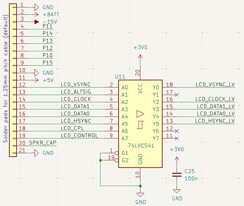
If you’re working with, for example, 3.3V logic, you might consider using a level shifter. A generic buffer like the 74LVC541 worked well in my use case.
Frame structure
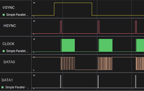
A frame contains all the data for one full image on the screen. In the case of the DMG, it is used to transfer 160x144 2-bit pixels. The process begins with the first pixel in the upper-left corner and continues horizontally. After 160 pixels, the next line is transferred until 144 lines have been sent to the display.

Each frame begins with a rising edge on the VSYNC line. The VSYNC signal stays high during the transfer of the first line and then returns to a low level for the rest of the frame.

Within a frame, you will find 144 lines, each initiated with a rising edge on the HSYNC line.

It seems there is some controversy about how the pixel clock works. I used an approach that I haven’t seen elsewhere (please email me if I’m wrong).
My first implementation just used the falling edge of the pixel clock (CLOCK line). I measured the pulses of the clock within the frame (160) and the alignment of the pixel data. This led to the obvious conclusion that the pixel data is valid on the falling edge of the clock.
![]()
After a while, I noticed some strange artifacts on the first column of pixels on the screen. Whenever a moving sprite leaves the screen on the right, it shows up pixel-wise on the first column on the left.
I searched for other projects that tried to capture the DMG screen and came across an article by Thomas Spurden (https://thomas.spurden.name/blog/capturing-gb-lcd/). He mentions a project by Sven Dahlstrand (https://github.com/svendahlstrand/game-boy-lcd-sniffing) that uses the same approach I did, and an article by Kevin Horton (http://blog.kevtris.org/blogfiles/Nitty%20Gritty%20Gameboy%20VRAM%20Timing.txt) which might have served as the signal interpretation blueprint for Thomas’ project.
Thomas and Kevin both say that the pixel data is valid on the rising edge of the pixel clock. Looking at the signals, this might be possible, but it would also be very strange from a design point of view. We are dealing with old (and cost-optimized) hardware, which might not be able to capture the signal fast enough. Even with modern hardware, it might be challenging to get it right. Additionally, this weakens the signal integrity when it comes to capacitive effects. Looking at the signals, the falling edge provides a nice sampling point at approximately 50%, which seems more likely to be the right approach in my opinion.
![]()
Thomas also mentions that the first pulse on the clock line should be ignored. I think he is correct. The position of the pulse in relation to the data looks a bit random compared to the other pulses. With the rising-edge approach, the capture of the last pixel (which, accordingly, has no pulse on the pixel clock) is done when the row is latched via the CPL signal.
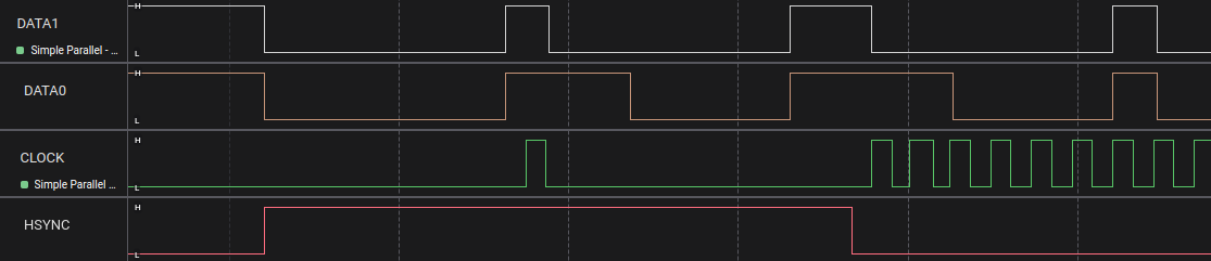
If the data is valid on the rising edge of the pixel clock, we would miss the first pixel when we focus on the falling edge instead. I wasn’t happy with this solution, so I did some more analysis on how to capture the first pixel while using the assumption that data is valid on the falling edge.
I used the title screen of Super Mario Land 2 for this. On the far-left column, there is a black line starting from the 15th row. This makes it easy to validate the first pixel of each row.

After some time, I found the pattern that the first pixel data is valid on the falling edge of HSYNC. Measurements also show that the timing is close, if not similar, to the pixel clock. In my opinion, this makes more sense from a design perspective than capturing on the rising edge.

I re-implemented my solution, which now works as follows:
- Wait for the rising edge on the VSYNC signal.
- Wait for the falling edge on the HSYNC line and capture data lines directly as the first pixel.
- Wait for the falling edge on the CLOCK line and capture data as the next pixel.
- Repeat step 3 for the next 158 pixels.
- Repeat from step 2 for the next 143 lines.
- Repeat from step 1.
I did some testing with Super Mario Land, Super Mario Land 2, Wario Land, and Pocket Bomberman. Everything looks quite stable. ;)
You can download some of my sample data from the Super Mario Land 2 title screen here (50MS/s dumped from Saleae Logic 2).
Please let me know if you find any issues with my approach.